Bosch ME7.1.1
Reading, writing and checksums
For reading and writing procedures refer to Reading and writing ECU (ME7.1.1)
Most flashing tools fix checksums automatically, if you wish to fix them manually, you can use LSuite
Definition file can be found here. If you are getting started with tuning with recommend consulting : Introduction to tuning
Terminology (Acronyms)
Maps and variables names are identified under acronyms. Knowing some of them will be useful and will help you remember map names.
Here is a list of the useful ones.
| Acronym | German | English |
|---|---|---|
| A | Auslaßnockenwelle aktiv | Exhaust camshaft active |
| AB | Abregelfaktor | Derating factor for acceleration signal |
| AL | Adaptation Lastbereich | Adaptation load range |
| ASR | Anti-slip regulation | |
| BB | Betriebsbedingungen | Operating conditions |
| BG | Berechnete Große | Calculated variable |
| BTS | Bauteilschutz | Component protection |
| CW | Code word | |
| DFPM | Diagnose-Fehlerpad-Managers | Diagnostic Faulth Path Manager |
| DK | Drosselklappe | Throttle valve |
| DS-S | Pressure sensor (MAP) on intake manifold | |
| E | Ersatzwert | Substitute value |
| ESUK | Einspritzung Ubergang Kompensation | Injection transition compensation |
| FA | Fahrer | Driver |
| FGR | FahrgeschwindigKeitsregler | Cruise control |
| FK | Faktor | Factor |
| FUEREG | Fullungreglers | Filling regulators |
| HFM | Hot film air mass sensor | |
| KF | Kennfeld | Map |
| KL | Kennlinie | Curve |
| KN | Klopfereignis | Knock event |
| KR | Klopfregelung | Knock control |
| KRA | KR-adaptation | KR-Adaptation |
| KUPPL | Kupplung | Clutch |
| KW | Kurbelvelle Grad | Crankshaft degrees |
| LL | Leerlauf | Idle |
| LLK | Leerlauf und geoffneter kupplung | Idle and open clutch |
| LLRBB | Leerlaufregelung Betriebs dedingungen | Idle control operating conditions |
| LU | Laufunruche | Unstediness / roughness |
| LUAR | Laufunruhe-Abstandsmass-Referenzwert | Rough running distance measure value |
| LUR | Laufunruche-Referenzwert | Rough running reference value |
| MBVH | Missbrauchverginderung | Abuse prevention |
| MI | Motormoment indiziertes | Indicated torque |
| ML | Motor Luftmassendurchsatz | Engine air mass flow |
| MN | Minimum | |
| MS | Massenstrom | Mass flow |
| MX | Maximum | |
| N | Normierter | Normalized / NM |
| NW | Nockenwellen | Camshafts |
| NWS | Nockenwellengsteverrung | Camshaft control |
| OP | Optimales | Optimal |
| PVD | Pressure vor Drosselklappe | Pressure in front of DK |
| RL | relative Luft | Relative air filling (load) |
| RLMIN | Relative mimale Luft | Relative minimal air (filling) |
| SA | Schubabschatten | Fuel cut-off / overrun |
| SOL | Soll | Should |
| SW | Schlechtwegstrecke | Rough road |
| TPKHFM | TemperaturKorrektur HFM | Temperature correction HFM |
| TUM | Umgebungstemperator | Ambient temperature |
| TV | Delay time | |
| UGD | Ungedroselt | Unthrottled |
| V | Verzogert | Delayed |
| WDK | DK-Winkel | DK angle |
| WKR | Winkelspatverstellung | Angle retard KR |
| WL | Warmlauf | Warm up |
| ZUL | Zulassig | Allowed limit |
| ZW | Zundungs Winkel | Ignition angle |
Engine management
The ME7.1.1 use a ST10F275 micro-controller. This set it apart from most ME7 ecus that use the Infineon C167_SR.
There are no public funktionsrahmen for the ME7.1.1. You will have to refer to the following funktionsrahmen : ME7.5 Funktionsrahmen, MED9.1 Funktionsrahmen and MED17.5 Funktionsrahmen
For the fuel injection and knock control system, you can refer to ME7.5 / MED9.1 FR.
Intake manifold pressure schemes are will be found on the MED17.5 FR.
Most other modules will be based on the MED9.1 architecture.
This ecu is load-dependent. Most map works with the requested load or the actual load.
Air mass
HFM (Aka MAF)
HFM5
The ME7.1.1 use a Bosch HFM5 sensor.
The HFM5 return an analog voltage signal to the ECU. The ECU use this sampled voltage value in the MSHFMU map to determine the air mass flow.
Over time voltage drop can happen in the signal wire, this will influence the measured value. For this reason, Bosch switched from a sampled voltage measurement to a sampled period measurement. Sampled period measurement is covered in HFM6.
For more informations regarding the HFM5 sensor, refer to HFM5.pdf
HFM6
The HFM6 is not used on ME7.1.1, but I believe covering this sensor is pertinent and interesting.
The HFM6 use a similar design to the HFM5. The bypass channel is flow-optimized compared to the HFM5.
The HFM6 transmit a digital signal for the measured air mass. The air mass measurement is evaluated by the frequency (period) instead of the signal voltage.
The advantage of using a digital signal is that voltage drop / interference does not influence the measurement, which make it more reliable than the HFM5. If the HFM fails, the ECU will use a substitute air-mass model stored in the ECU, like the BGMSDK module (Calculation from throttle angle)
Reverse flow / pulsations
On some conditions (like intake valve closing, for example), the air might go back through the HFM and influence the readings. Different displacement elements can influence pulsation. To correct these pulsations, the ECU will rely on pulsation map : KFPU, KFPUKL1
The ECU will select a specific pulsation map depending on which elements are influencing pulsations. When using an aftermarket MAF, if you do not wish to deal with those maps, you can set the pulsation maps to 1.0 to disable the pulsation compensations. It should not have much incidence on the engine safety. Please keep in mind that while the engine is on "boost", the HFM is not affected by reverse flow or pulsations. The pulsation compensations are in place to ensure an accurate air mass reading at all-time which lead to more control for stoichiometric AFR thus resulting in better emissions.
BGMSDK (Calculation from throttle valve angle)
This module calculate an air mass flow based of the throttle valve angle, a pressure ratio (intake manifold pressure / the pressure before the throttle valve) and the gas temperature (since it affects air density)
The map KFMSNWDKVP stores the air mass flow depending of the opening angle and the pressure ratio according to the following standards:
- Pressure in front of throttle valve (before) = 1013 hPa
- Gas temperature = 0°C
A pressure and a temperature correction factor is applied to to the standarized mass air flow (Respectively, ftvdk and fpvdk).
*Gas velocity is equal to the speed of sound under a pressure ratio of 0.528
*Interesting to note the temperature correction factor (ftvdk) formula:
Disabling DTC
The DTC are stored under error class that are defined in a "DTC table". The index at which a certain error class/DTC is stored in the DTC table can be calculated with a simple formula.
Before getting started, you should define the following address that you will use for calculations:
- CDC (CARB codes, OBD2 generic) start address : CDCAAA
- CDK (Kundle (Customer) / Manufacturers codes) : CDKAAA
- CLA (Error class aka DTC table) : CLAAAA
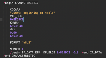
You can use the .A2L file that match your ECU:
In this case the CDC start address would be 0xE59C2. (The offset of 0x800000 has been substracted from the address)
Once the start address are defined, we can proceed to the calculation of the DTC index.
For generic codes (Starts with P0XXX):
We will use the table CDC
For manufacturer code:
We will use the table CDK
Finding the index
Let's assume we want to remove the code P0302, this is a generic code, so we will be using the table CDC.
In WinOLS (or your map editor of choice), set the view in 16bits, FF, LoHi
Go to (Control-G) the start address of CDC, in this example it would be 0xE59C2
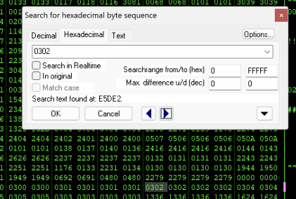
Search for an hexadecimal (using Control-F) with the DTC code : 0302
You should see 0302 repeating 4 times, we want the address of the first occurence of the block of 4. If you see a block of 6, ignore the first two occurences.
The address of the first occurence of 0302 would be 0xE5DE2.
Now to get the index we use this formula :
Index = (address of the first occurence - start address of the table) / 8
In our example it would be :
(0xE5DE2 - 0xE59C2) / 8 = 0x84
Index is 0x84
Locating the error class in the CLA table
Using the start address provided by CLAAAA, use the following formula:
CLA error class address = CLA start address (CLAAAA) + index
In our example it would be :
CLA error class address = 0xE05B1 + 0x84 = 0xE0635
The address 0xE0635 contains the error class for the DTC P0302.
To disable the DTC set the byte at the address 0xE0635 to 0.


