Funktionsrahmen
What is a funktionsrahmen
Funktionsrahmen could be translated to "Functional framework". It's a document documenting all the modules that compose an ECU program.
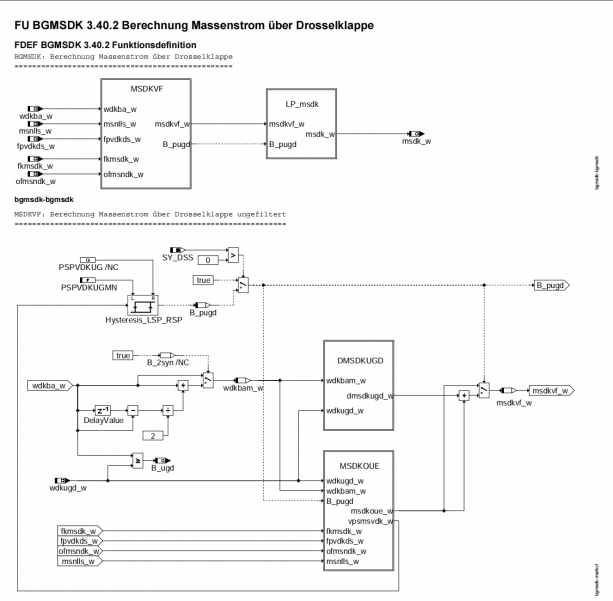
For every module, there is a quick definition, logic diagrams for every sub-functions:
Then the variables and constants are defined :
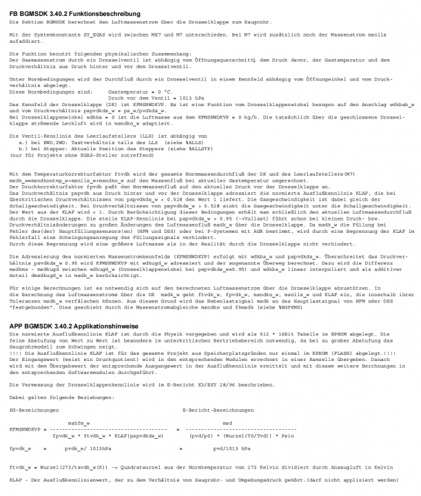
Finally, there is a more detailed description of the module and some application notes:
Understanding the logic diagrams
We read the diagram from left to right.
Logic gates
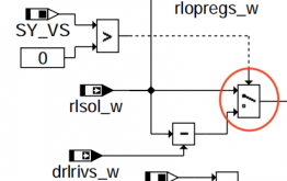
What we see on the above diagram, the default state of the logic gate would be to use the variable "rlsol_w".
The doted line represent the condition needed to switch the logic gate to a different state. In this instance, if the constant "SY_VS" is greater than "0" (SY_VS > 0), then the logic gate will use the variable "drlrivs_w".
Operators
These operators are self-explanatory
MN will take the smallest of the two variables.
MX will take the biggest of the two variables.
This is the equivalent of "inverse / not / negative". If the value is true (>0), this will ouput false (0). If the value is false (0), then it will output true(>0).
This mean it is using the value of a map, the MAP is indicated below the "icon".


