Immobilizer Removal
ME7.1.1

To remove the immobilizer, we will need to read the EEPROM
Reading the EEPROM
You will need the following :
- 1K or 2K ohm resistor
- A VAG KKL cable or any cable with a FTDI (FT232) chip
- A power source to supply the ecu on bench
- ME7EEPROM_st10.exe
- A hex editor software (You can use the one from TunerPro)
Open the ecu, you can refer here for instructions : Opening the ecu
To supply power to the ecu off the car, you can make your own harness or use one of these (81 pin ME7 OBD2 Adapater):


If you wish to make your own harness you can find the pinout here: ME7.1.1 Pinout, OBD2 Pinout

Powering up the ECU in boot mode

- Before powering up the ECU, you need to ground the boot pin and put your resistor as shown above
- Now you can power up the ecu, wait about 2 seconds and remove the resistor
- The ecu should now be in boot mode (I noticed that the ecu generally runs under 300mA when in boot mode, if you see higher amperage, it's probably not in boot mode)
Using ME7EEPROM to read / write

COM port settings
- On your Windows, open the Device manager
- Go into Communications ports, find the device that correspond to your cable.
- Double click on it, a properties window should open
- In the Port settings change Bits per second to 9600
- Take note of the COM port number (COM1 would be 1)
Open a terminal (In the search bar, type cmd), go into the directory where ME7EEPROM_st10.exe is located.

To read the EEPROM type in the following command (adapt the parameters for your usage):
ME7EEPROM_st10.exe -p 1 –b 9600 –bootmode 95160 –r immo_on.bin –CSpin P6.3
- -p : Your COM port
- -b : baudrate, we set it previously to 9600 (Some ecus revisions need to use an higher baudrate like 57600)
- --bootmode : Required for ME7.1.1 ecu. Equipped with a 95160 EEPROM chipset
- -r : Read the EEPROM and save it into the filename immo_on.bin
- --CSpin : Keep it a P6.3. Most ME7 ecu use P4.7, but for our specific ME7 with a ST10F microcontroller, it uses P6.3
Disabling the EEPROM from the file
In your hex edit, open the file immo_on.bin. Change the following values (If hex adresses are confusing, refer to the images):
- At 0012 and 0022, change 01 to 02 (This is immobilizer status, 2 = not active)
- At 001E and 002E, remove 1 from actual value (These are the checksums)


Save the modified file under the name immo_off.bin. Turn off the ecu, power it back on boot mode.
Using ME7EEPROM_st10.exe, type in the following command to write back the ecu (adapt the parameters for your usage):
ME7EEPROM_st10.exe -p 1 –b 9600 –bootmode 95160 –w immo_off.bin –CSpin P6.3
- -w : Write the file immo_off.bin into the EEPROM
The writing process take some take and will indicate "error" at the end. This is normal, you can read back the ecu to confirm the modifications has been applied.
ME17.5
Read the flash memory from the ECU using the method of your choice (Refer to Reading and writing ECU)
Using an hex editor (TunerPro provides one), find the following sequence:
ME17.5
BF E2 F6 FF 0C EE
ME17.5.6
BF E0 F7 FF 0C DE
And replace it by this one:
ME17.5
BF E2 F6 FF 82 2F
ME17.5.6
BF E0 F7 FF 82 2F
Prior flashing the file back into the ECU, you should fix the checksums, multiple flashing tools does it for you, but you should fix them yourself by precaution
In-depth explanation
Using a2lextract, open the .ecu file that correspond to the definition file (.a2l) that match your ECU
Locate the variable u_immo

Offset the address by 4 : D0000130 would become D0000134 in this case
In your disassembly tool, look for the following label : word_[your address] (in IDA, you can press G to goto a label)
![]()
Now find the reference to this label (in IDA, you can press X)

Look for a st.h instruction that use d15 and access it

Above your st.h instruction, you have a ld.bu instruction that set d15 to [a13]0xE
(If you don't find those instructions, you can search for occurrences of either [a13]0xE or [a14]0xE)
To disable the immobilizer, we will change the ld16.bu to a mov16 instruction in order to set d15 to 2:
- Select the ld16.bu instruction, go to Hex View
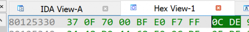
- Press F2 to edit the hex and replace the selected instruction by 82 2F, press F2 again


Now d15 is set to 2:
![]()
Save your file and you're done